Event
Mosaic Creator -
Help Event
Mosaic Creator -
Help |
Event
Mosaic Creator -
Help
Tools
The Tools tab has a couple a useful
functions. These are located in 8 sub tabs. Each of these functions is described in this
chapter. What you should know about placement sequencing When you
select a placement sequence (random, density map) the application will
precalculate the placement sequence for the entire mosaic. This data
is stored in a file, and is used the next time the
mosaic is resumed. Each image that is processed is checked for next location, and is processed to
fit at the location in the source image. This means that the colour
matching is poor, and that heavy colour corrections of the new image may be required,
where the colours of the image can become unnaturally strange. This holds for the colours
only, since the gray-values of the #tag image will remain intact (but will
change when blending is applied). Therefore, by removing an image, the sequence is
broken because that earlier image should now be placed back as the next
in the sequence. The application however does only remove the pointer of that
location, leaving it empty. As a consequence, the next image that is processed
finds this early but now void location, and refills it, placing the new image
at the removed location. This way replacement is immediate.
However, when you
select the default option of placement, the 'optmized colours', The replacement
of an earlier placed image can wait for some time. Thsi is because the
application only selects a next location based on the colour matching content of
the new image and the still free source locations.
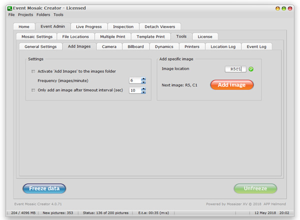
2. Add images
The folder
'library' is used for this feature. In this folder
you may have put prepared images (we call these 'a library of images'), that can
be used to complete the mosaic (if
images are not sent any more, but still incomplete), or when unusual colours are required, and
needs to be made available. Or for whatever reason you want to manage the images yourself,
rather than depending on the unpredictable nature of #tag images.
Settings are quite simple: Activate 'Add Images' to the
images folder will initiate an action to select one of your prepared
images, instead of a grabbed #tag image. The frequency is indicates as how many
times per minute. The Only add an image after timeout
interval (sec) will only grab an image from your
own library folder when a certain idle time was detected (=
no new #tag image was uploaded). This is a great way to keep the images flowing
in, allowing a better control of the timeline of mosaic completion. Finally,
the folder indicated in this tab is the images folder where your prepared images
are stored. You should make sure that sufficient images
are available (1000 or more would be great). When all the images have
been added, the sequence starts again. So, when few images are found in
your folder, an image can be used more than once in your mosaic. When
all the images in the library folder are used, the addition will automatically stop. The option 'Add specific
image' is described here. 3. The
Camera The 3rd tab is a dedicated tab in case an on-site camera
is used, e.g. tethered shooting, or via WiFi, saving the image to the watched
folder. There are two functions: chroma keying and skin/face detection. Chroma-keying A chroma key will effectively delete the background of an image with a certain colour.
In many cases a green (or blue) screen is used, agiants whihc a person is photographed.
The application can manage chroma keying effectively: The chroma-key settings are saved in the project and is
also frozen after fixing the settings. The horizontal explorer in the
tab reflects all the current images in the Watched
folder (so: not the Waiting room). The chroma key can be set during an event to finetune
the chroma key, but it's highly recommended to manage the lighting of the
screen effectively, to assure a proper deletion of the
background. The transparent image will be placed on a tile, where the corresponding tile
from the source image is used as the background. In case the user
has set blend and colorize as well, these will only be effective for
the opague image, since the background is already in
place. Skin detection
This feature will try to identify the skin by analysing
the image, and estimating the colours that are most likely to be human skin. The
method uses parametric data, so the skin might not always be detected
effectively. It not only will find faces, but also (bare) arms and hands. After
detection of the skin in the (snapshot) image, it will then create a cut-out
area, which will be used for the print. This cut-out area can be made slightly
larger by setting a value for 'Detection enlargement'
in percentage of the cut-out part. When enlargment is not
possible (e.g. outside the image) it will try to maximize the cutout
within the enlargement as much as possible. It can also take care of
non-squareness in case rectangular images are chosen in the
mosaic. Face detection
This feature will try to identify the face using the open
source algorithms from OpenCV (opencv.org).
The method uses trained face detection data (as defined in the file 'haarcascade_frontalface_alt.xml'). After
detection of the face in the (snapshot) image, it will then create a cut-out
area, which will be used for the print. This cut-out area can be made slightly
larger by setting a value for 'Detection enlargement'
in percentage of the cut-out part. When enlargment is not
possible (e.g. outside the image) it will try to maximize the cutout
within the enlargement as much as possible. It can also take care of
non-squareness in case rectangular images are chosen in the
mosaic. The skin and face recognition works best with natural
light and sufficient light. It can detect faces and skins from different
skin-types, like African, East-Asian, Caucasian, Indian, and Nordic.
Extremely dark and extremely light skins may be detected wrongly, as may be
hair, in the teint of skin. Also when shiny skins are found, e.g. by reflecting
light on the skin, the colours may be detected wrongly or incomplete. This
feature is supported, is in constant development, and will be improved
in new released. The face detection method is not 100% accurate.
This may be the case for objects that
obstruct the detection, such as artifacts (hats, glasses), and other parts of the body, e.g. hands.
In most cases lateral faces are recognized, but also not 100% proof.
In case of doubt, the skin is skightly more accurate in finding the
skin areas, and draw a rectangle for the proper
cut-out. 4. The Billboard This is a tool to create the Billboard on which the
images can be stuck. Although Billboards can become huge (several meters in
size), the print-out from this tab can be useful for those who want to prepare
for an on-the-fly Billboard. In the
above screenshot a white Billboard is shown,
of size 20x10 tiles. The print image size was set to 4x4 inch, so the entire
Billboard would have been (when printed) 80x40 inch. The area on the left
shows the detailed squares with the RC (here in Excel format) locations. On the
right a few controls are seen: Two other
Billboard output options are available as bitmap images:
as Photoshop (.psd) or as a Portable Network Graphics (.png) file. Both
are saved in transparent mode by default. The .png file is usually 2x-4x smaller
than the .psd file (less overhead data). The print density (dpi) is defaulted to
300, but in case the Billboard is too large (> 350 MB) then the dpi values
will be lowered until below this maximum (bitmap) size. The advantage of this
approach is that always maximum size is achieved, but the downside is that since
bitmap images are less suitable for scaling up, some pixels 'imperfections' (due
to scale up) may become visible. The two output files are then called
'Billboard.psd' and 'Billboard.png'. At the
bottom of this tab you find the button to refresh the billboard design
(sometimes this is needed), and the option to invert
the colours. This will result in a black background, and gray lines. For
.psd and .png output the black colour option is not available, since the
background is made transparent. Please be aware to print several square meters
of black may seriously drain the toner of your printer.... 5. Dynamics
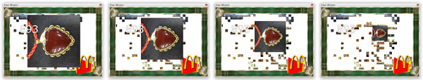
In this tab an exciting feature is
provided: dynamic tile placement. Each tile can be placed into the mosaic, showing
on screen, in a dynamic way: In this tab
the settings for the Dynamics is all about making the
mosaic come alive. This only makes sense when you detach a viewer and show it on
a monitor. Do not use this option if you don't use a monitor to follow the
mosaic build-up. This is because the dynamics not only require quite some
computing power, it also slows down tile placement because it has to complete
the dynamic cycle first. This sequence example shows a
typical result (4 frames taken from a dynamic cycle). It shows the initial size
(almost filling the entire space), and gradually decreasing to fit the final size in the
mosaic. The settings are: What you need to know about tile
dynamics Tile dynamics require time ànd computing power. If you
would like a smooth dynamic movement, then 20-30 frames per second would be a
good value. But calculating 30 frames, for a 3-second animation will take some
time. Our test system (Intel i5, 4th Gen), takes 3 seconds to calculate these
images, and store them in RAM, ready for seamless dynamics. That means that a
dynamic cycle can easily add up to 10 seconds or more (e.g. 3 seconds of
creating the frames, 2 seconds static showing before starting the flying
action, 3 seconds of flying and 2 more seconds of pre/post-blend). That would be
6 images per minute, 360 per hour. A 100 x 50 tile mosaic will then take
almost 14 hours. Non-stop. Speeding up can be done by lowering the framerate (20
fps would suffice), shorter static time, shorter flying time, shorter blend. A
good compromise is 2 + 1 + 2 + 1.5 = 6.5 sec/tile, or 550 per hour, or 9
hours to complete the 100 x 50 tile mosaic. Of course making the mosaic smaller
is also a good option. Bottomline: do the maths before starting to use
dynamics!
6. The print Layout
tab
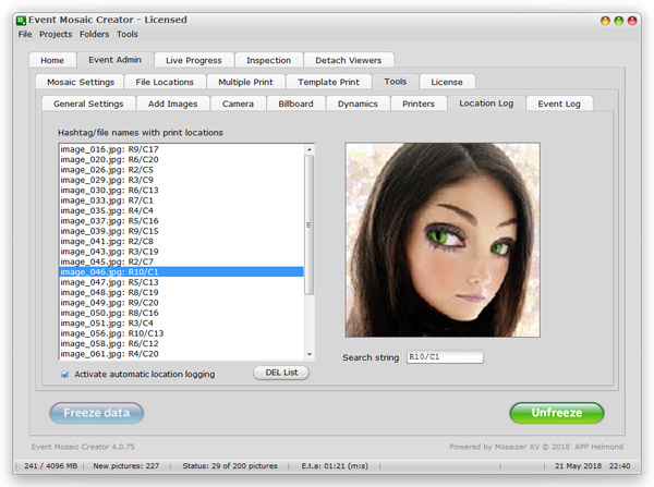
In this
tab only a single feature is found: the placement log for each image. In the
above screenshot you can see the image filename and the placed location. Here it
is a name that is concatenated from of the date and the filename. An alternative
notation would be in Row and Column coordinates, like R4/C21, which is equal to
U4. The notation choice is described here. The example above shows the
location in RC coordinates. In addition, a search option is provided, to
locate certain images for a certain location, and the corresponding image. This
might be useful to find an image if someone wants a new print. To find an image,
just start typing the location string (in the current format), and it will show
the corresponding image, if it can find it (=
if an image
is placed at the typed location). Doubleclick on the image will open that
image in the
default Windows photo viewer, from where you can
(re)print, copy, e-mail etc. the image.
Note: The search string (here:
R10/C1) must be a valid location code. When typing the suggested image is
shown. The image is only shown when the indicated location code is correct, and has a
placed image. Also by scrolling over the list on the left will
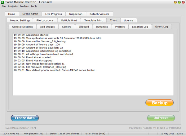
show the corresponding (placed) image. 8. The event logger The Event
logger can also be regarded as an admin tool. It logs the notifications and key
actions of the application. In case of an error this log will usually show the
source (or at least a code or remark what happened), and a dump of this list is
saved on the Desktop. The file is named 'Event Mosaic
Creator.txt'. In this tab you also find the 'Backup' button. This will create a full backup of
the selected 'Watched' folder. In case you have manually changed the locations, the backup
will read the data, but will be saving it in the default folder structure in the
zip file (the output file of the backup). The backup file will be saved on the
Desktop. After backup has completed, you are asked to also remove all the data,
starting with a clean sheet for a next event.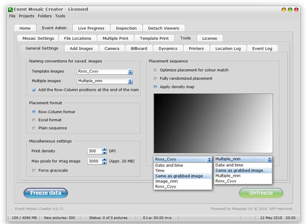
Naming conventions for saved images.
Here you can be more specific what the
file-naming must be used to store #tag images that are processed. This is
not the same as the name of the #tag images; these are managed in your #tag grabbing
tool, like the freeware 4K Stogram application. The file-naming options are
different from multiple and single image templates. The options are also shown
in the screenshot above (shaded pull-down boxes, added on the right by
Photoshop editing). The files that follow this naming convention are stored in
the folder 'Watched\saved'. The last option
'Add the Row-Column positions at the end of the
name' is to also add the RC location to each file. This
is only useful for single image templates.
Placement format. Here you can
select what kind of placement location format you would like to apply.
The 'Row-Column format' is e.g. R21/C43, where the
'Excel format' would translate that exaple as AQ21.
The 'Plain sequence' format is simply counting,
from top to bottom, row by row. Note: The example of R21/C43 can
not be translated in plain sequence, because we didin't specifiy how many rows
the mosaic has. If we would use the example of R12/C1, the
plain format sequence number would be 12.
Print density. The dpi value of the
saved prints. In some cases printers require a certain print density value to
correctly scale the print. The default of 300 dpi should be kept as much as
possible (and to avoid large files and processing time), so be careful when
changing this number to a higher value. The maximum value is 1200 dpi, in
increments of 50 dpi. This maximum is not a really useful value (very large
files, long processing time), but if the user insists on extremely high
quality prints, the option is there (do the maths: 1200 dpi of a 4x4 inch
print =
4800x4800
pixels, or 68 MB bitmap to process!).
Force grayscale. In case you wish to
create a fully colourless (grayscale) mosaic, you can force the #tag images to
become gray
(remove colours), and also to make the source image gray. The
consequence is that 'Colorize' won't work, and the only way to
assure that the mosaic resembles the source image os by heavy blending, up
to 80%. Alternatively is using many images, but this is no guarantee
that the end result still looks good.
Placement sequence. There are three
different approaches to build the mosaic. The first is the 'classic' approach:
find the best possible fit for the colours. The second is a fully random
approach, where each image can basically be placed anywhere. The third
approach uses a so-called 'density-mask', where
the sequence is determined by the pixel value of the corresponding location of
the density mask with the location in the moasic. The density mask must
therefore be of equal size ratio as the source image. An ideal density mask is
as large in pixels, as the amount of images in the mosaic. So, e.g. a mosaic
of 120x60 images would then need a 120x60 pixels mask, where you can
determine how the sequence would need to be. In the example above the mosaic
is building up from the top-left, oblique to right-bottom. The darkest pixels
are placed first (=
0 byte gray scale), counting down to
the whitest pixels (=
255 byte gray scale). We have
pre-installed a couple of examples to experiment with.
The
placement approaches are also referred to as 'sequenced' (density mask, fully
randomized) and 'optimized'
(or 'non-sequenced'). This is because
in sequenced placement a full placement sequence is created for all the tiles. Only the
colour optimized approach is non-pre-sequenced. This is important to understand in case
you wish to remove/replace already placed images (next
paragraph).
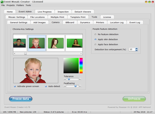
Click on the green background in the picture
(example: the hoodie-guy). This is the selected chroma key, and the (green)
colour will immediately be made transparent. The Tolerance is the amount of
similar colour that is also made transparent, while the Feathering
will crerate a certain edge from transparent to
opague.
Click on the colour patch (HSV
colours) to select your chroma key. The effect is
immediate.
The 'Auto detect' option
will activate a chrome-guess approach, where the chroma key colour is
estimated for each individual image. The tolerance is preset, so also the
guess key has this tolerance. Our tests have shown that too much variation
in green screen lighting may result in strange chroma key choices. In
general when the lighting is consistent, the chroma keying works flawless. One
word of caution: the screen should not have shadows and wrinkles, and it
should not stop inside the image frame (e.g. parts of the background are
not green). It basically requires a
professional green screen set-up, like any other chroma keying
event.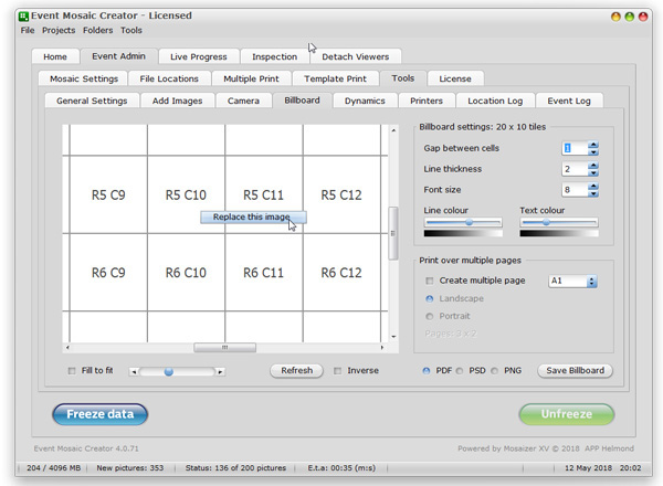
Billboard settings. You can create a little Gap between each cell (=image), but only on the
Billboard. The images will still be stuck seamlessly. Also the Line thickness can be indicated (in pixels), and the
font size
(relative to the size of the square, not real picas or pts). Also the
Line colour (as gray value) and the Text colour can be set.
Print over multiple pages. In many cases you don't have
the possibility to print the entire Billboard on one sheet of paper. In that
case the application will conveniently cut the Billboard into smaller parts of
the indicated size. The size can be set from ANSI Letter /
ISO A4 to ISO A0. Also the paper orientation
(landscape or portrait) can be set to help
to minimize the waste when a Billboard does not match with the size of the
accumulated sheets of paper. The small diagram shows the actual mosaic size in
light gray, and the pages in white, with dark gray lines. You can activate
this option by checking the tickbox Create multiple
pages.
The printed result is saved as a pdf file. This file
already has the correct size settings, and when sent to a printer it will
print the actual size. Since the application formats the pdf in vector format,
the print quality is impeccable, and follows the quality of the printer. The
file is named 'Billboard.pdf', and is always saved on your Desktop. The
Billboard is created when you press the 'Save
Billboard'
button. The PDF file will be opened (and you
can now save the Billboard file as well), the other two options will save the
Billboard on the Desktop. 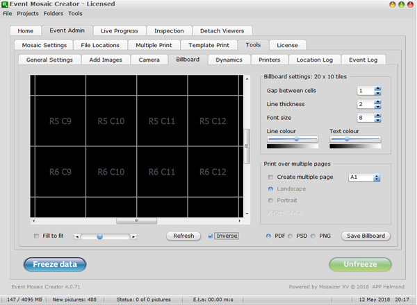
Slowly emerging in full size (as if
it emerges into the existing mosaic).
'Flying' the image towards the destination, while the
image get smaller to fit in.
Blending with the coloured version of the image (in
most cases each image gets the colour of the source image).
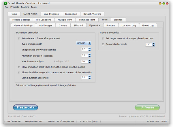
Animate each frame after placement.
This is a kind of timer of the animation. The image is show for a certain
period of time (Image static), then animated
(dynamically frying towards its location (Animation
duration) and at a
certain Frame rate.
Slow animation start when flying the image into the
mosaic. The animation can start slowly, and end slowly (although the latter might not
be visible very well because it's getting smaller and smaller). This option will show
the image slightly longer at start, and then fly in quickly, and
slows down to meet
its final destination.
Type of flying path. There are three options: linear,
circular and spiralled. This is the type of movement that the image
will make when flying
towards its destination.
Demonstrator mode. This will repeatedly show a mosaic
being built up from your current images folder, where images
fly in all the time. This might be an attractive mode to get people
on board. The flying mode will only be visible on the same detached viewer,
so this cannot be shown during an actual live event. You need
a second system to
make this happen.
Set target amount on images placed per hour. When this
option is checked, the application will try to trigger a new image such, that
the target amount of images per hour is placed and printed. All functions behave
as a normal (watched folder) triggered event. The only difference is that
triggering is done in
a controlled manner.
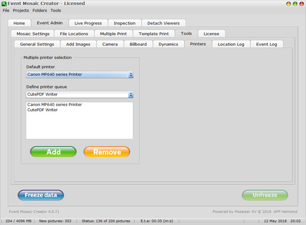
The user can apply more than one printer.
This is useful when many images need to be printed in a limited time. In
this functional tab, printers can be selected and added to the printer pool. The
default printer is already active, the list above the two coloured buttons. The
dropdown selection box contains all the printers active in your system. Select a
printer you'd like to add, and then press the Add
button. The name of the printer will now be added to the list. To remove a
printer (e.g. you accidentally added a .pdf writer), select the printer in the
overview, and then press the Remove
button. The printer will be
removed. You cannot delete the last printer, because at least one printer must be
available. In case you don't want to print, there is no need to manage the list.
Every windows system has a default printer (e.g. Microsoft XPS or Fax printers),
and then the default will be shown in the selection box. Of course, when you
want to add a newly installed printer, you must always check if this overview
still has the correct printer selected. Avoid using printers
that require an interaction, like pdf writers.
7. The Location Log
tab